Super Display: An open-source physical display of welcome text in Nigerian languages
Background
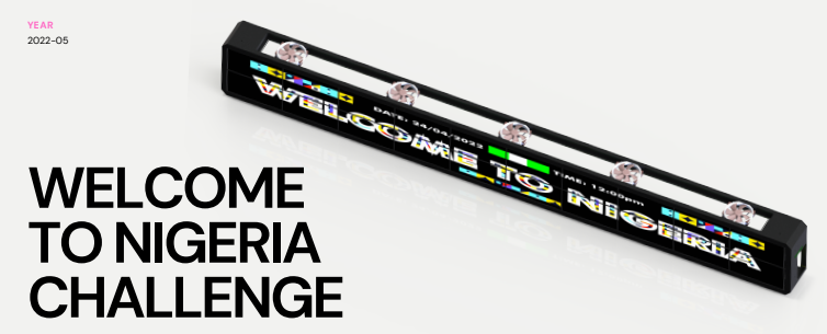
Figure 1: An overview of the Super Display concept.
The Welcome To Nigeria Challenge was conceived to give Nigeria’s busiest airport a much-needed emotional touch. After the first round, one team was selected by the judges to develop their concept, named Super Display into a full-fledged product. In order to design a physical interface that lists ‘Welcome’ in every Nigerian language, the interface would need to be clearly visible from a distance and may incorporate other signals (such as audio, etc) as it would be displayed in Nigerian international airports or other locations. The product should also have the ability to be updated with new languages.
This documentation provides the instructions for anyone to build a Super Display of their own. It is licensed CC BY-SA 4.0; attribution should be made to the team members as well as Hardware Things.
NOTE: While the product can be built with the PCB file attached above, the current version does not use this. It uses the ESP 32 for its control. We describe how the PCB may be used in the Extensions section.
Build Instructions
Frame Assembly
To make the frame you will need the following aluminium parts (see the mechanical design files), note that the last two are assembly hardware:
Item
Quantity
Dimensions [LxBxH]
S1, S2
1 of each
[324x40x40mm]
T1, T2, T7, T8
1 of each
[802x40x40mm]
T3, T5, T4, T8
1 of each
[800x40x40mm]
J1, J2, J3, J4
1 of each
[40x40x40mm]
Internal Rail
18
[160x20x20mm]
Brace (M1)
3
[324x40x3mm]
LINK
6
[40x22.5x40mm]
M2.5 Cross Head 14mm
108
see BOM
M3 Cross Head 8mm
52
see BOM
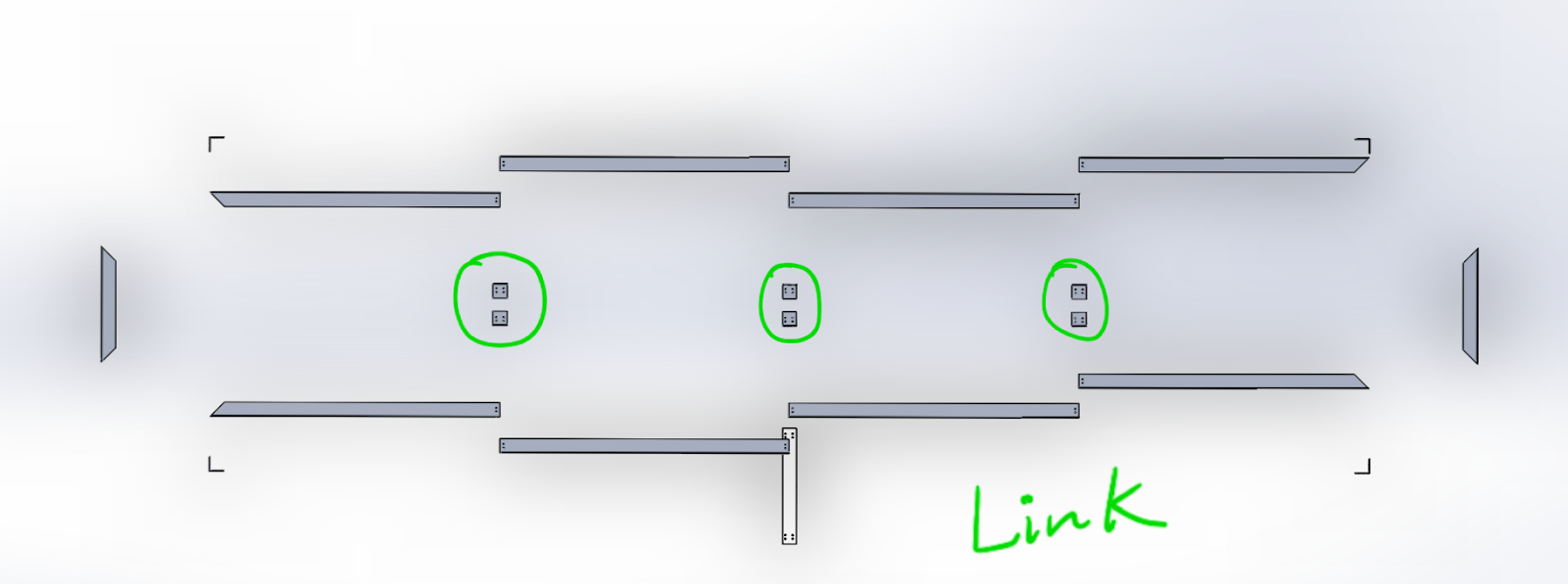
Use LINK to fasten T3 to T1, then T5 to T3, then T7 to T5, then T4 to T2, then T6 to T4, and T8 to T6. See Figures 3 and 4 for layout.
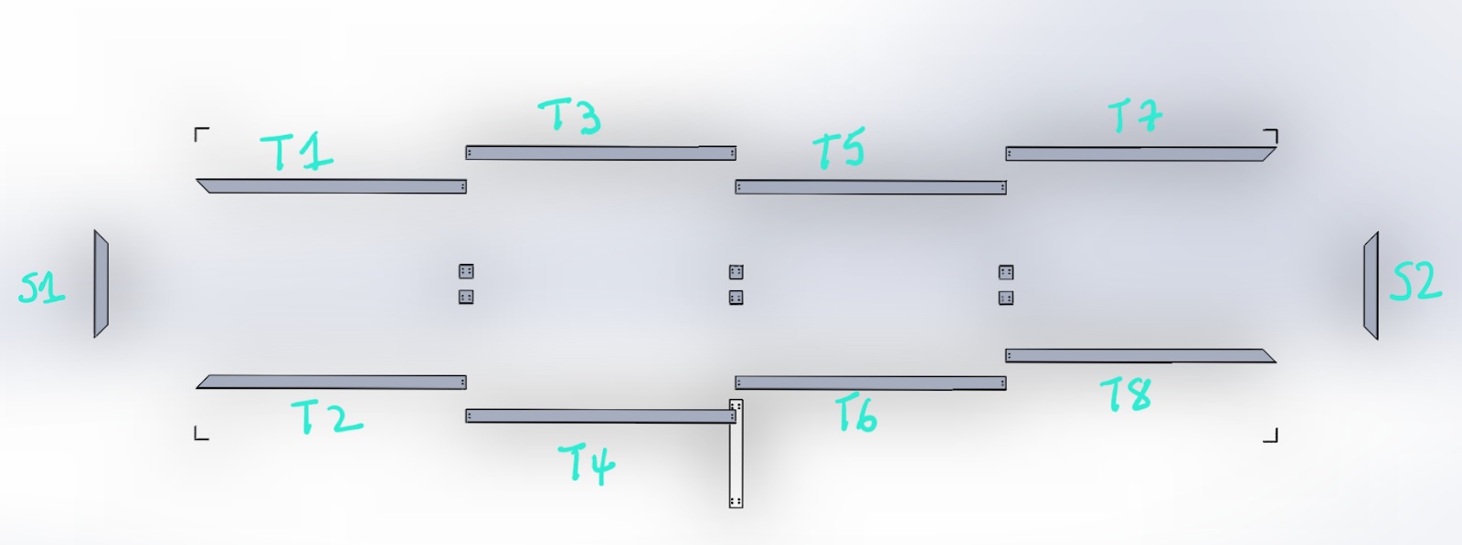
Figure 3: Layout of the basic assembly showing the aluminium parts.Figure 4: Layout of the basic assembly showing the configuration of the links.
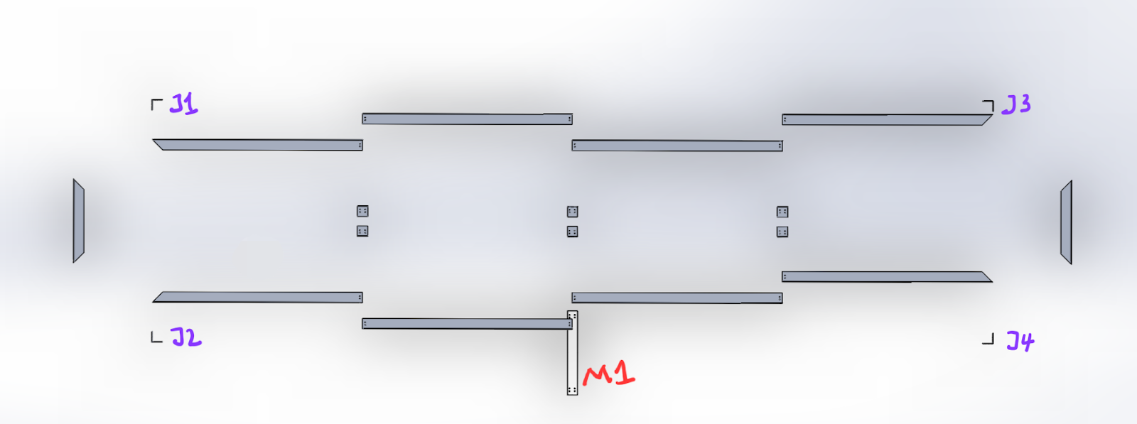
Next, Use J1 to fasten S1 to T1, then use J2 to fasten S1 & T2, then use J3 to fasten T7 to S2, then use J4 to fasten T8 to S2, and use M1 to brace T3, T5, T4, & T6 together. See Figure 5 for the layout and Figures 6 and 7 for the assembly process.
Figure 5: Layout of the basic assembly showing J1, J2, J3, J4, and M1.Figure 6: Back view of full assembly process (GIF).Figure 7: Front view of full assembly process (GIF).
NOTES:
Fabrication of the display frame will require 24.41ft of 40mm Aluminum angle.
Holes in some 3D printed parts may not fit accurately. Print without holes, drill after.
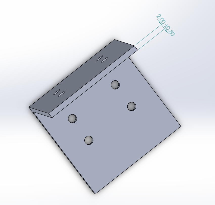
The Aluminum angles available locally are in several colloquially named variants. Use parts with 2mm thickness (see Figure 8 below). Thicker ones are heavier, and may overload the mount.
Figure 8: An aluminium angle part.
Display Assembly
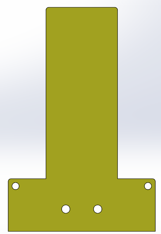
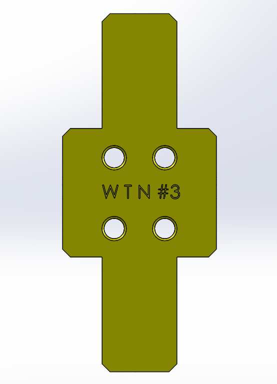
Assembling the display requires 9 bulk to display mounts. Each mount requires three 3D printed parts (see Mechanical Design files for this) as shown below. 2 DP1 parts are requires, while 1 DP2 part is also required.
Figure 9: DP1 (left) and DP2 (right).
To assemble one bulk to display mount, join two DP1 parts together and then fit DP2 on, as shown below in Figure 10.
Figure 10: Bulk to display mounts assembly process (GIF).
After that, use the assembled mount pieces to fasten the P5 Matrix LED panels together as shown in the Figure 11 animation.
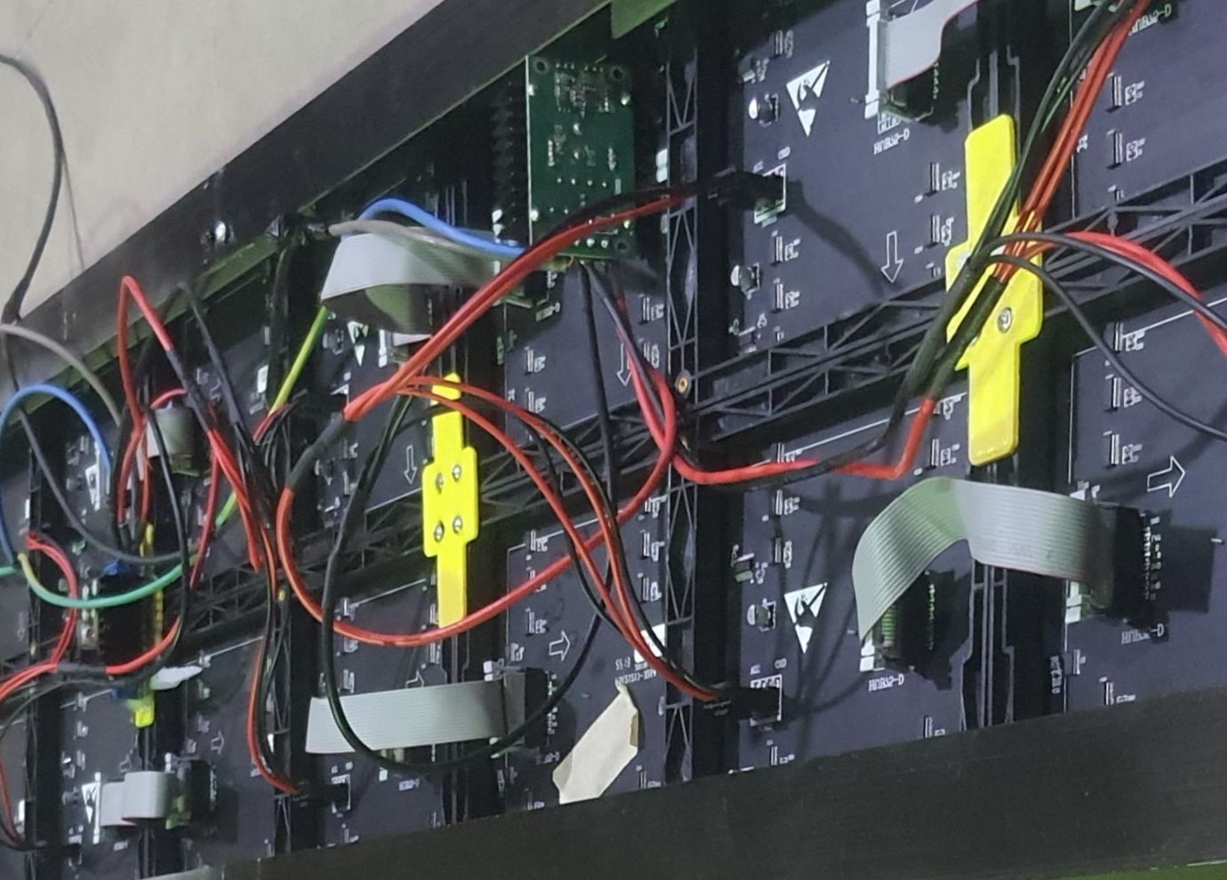
Figure 11: Assembly process of the full P5 display unit (GIF).Figure 12: Back view of assembled display unit showing the bulk to display mounts in yellow.
Connecting the Electronics
To make the battery pack you will need the following parts:
Item
Quantity
P5LED matrix display
20
300w bulk converter
5
4mm wire cable
5 yards
Take the following steps:
Mount all the display to the frame while making sure all arrows are pointing in the same direction.
Connect the displays on the same row with hub75 connector (white cable).
Connect WF2 controller to the first led matrix.
Connect each bulk converter to the charger and turn the potentiometer till the output voltage is 5V.
Connect 4 led matrix to one 300W bulk converter.
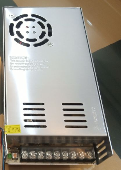
Connect the 9V30A charger to mains power supply.
Connect the batteries to the charger.
Connect the charger to each bulk convert input port with the 4mm cable(blue and yellow cable).
Connect the WF2 controller to one of the bulk converter’s outputs for power.
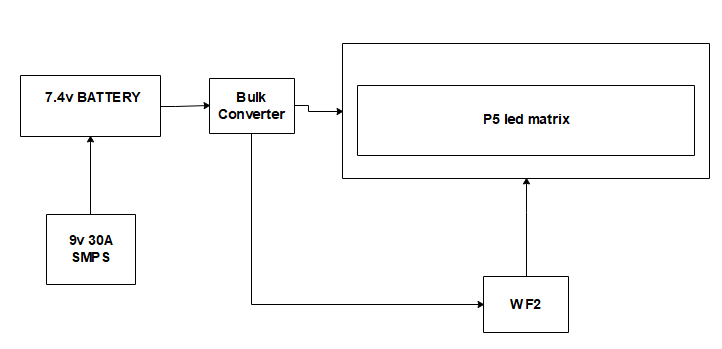
Figure 13: Connection diagram.
Figure 12 also shows the electronic connection when completed.
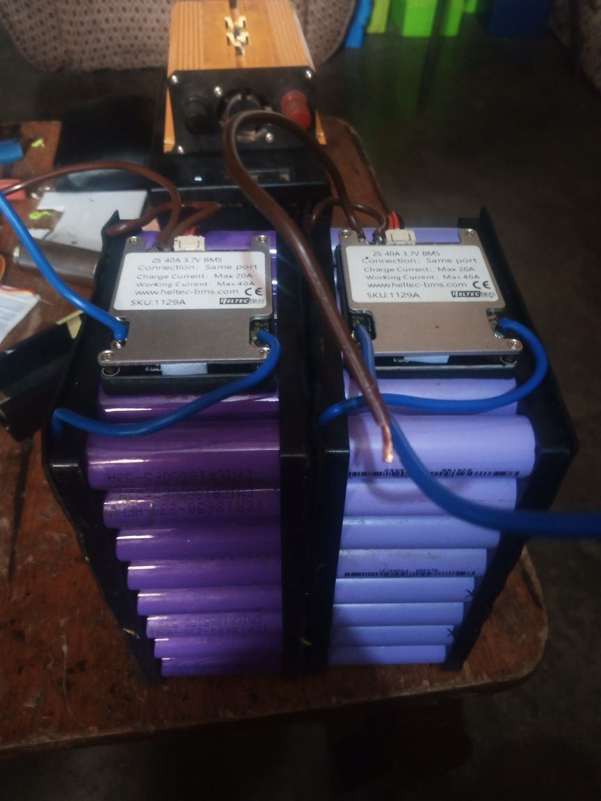
Battery Unit
The battery is made of 96 2200mAh 18650 lithium ion cells made into two battery packs (48 cells each) 6 by 8 configuration. Each battery pack is connected to 40 Amps 2s BMS. The battery packs are charged with a 9V 30 Amps power supply. To make the battery pack you need the following:
Item
Quantity
18650 2200mAh lithium ion cells
96
18650 combination bracket
96
0.15x8mm nickel strip
10 meters
Insulating pad
Spot welder
40A 2s BMS
2
4mm wire cable
Take the following steps to make the battery pack:
Interlock the 18650 combination bracket to form two 6 by 8 boxes.
Arrange 48 cells on each box as shown below.
Connect the battery together (2s 24p) with the spot welder and the nickel stripe (see Figure 14).
Figure 14: Battery connection.
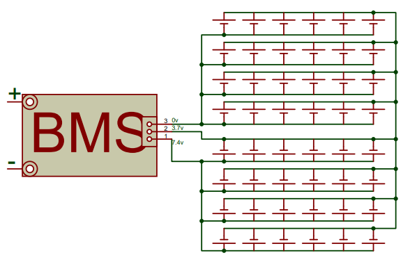
Connect the battery packs to the bms according to the diagram below.
Figure 15a (left): Schematic of BMS connection (left); Figure 15b (right): The first 3 pins on the left are ground pins, followed by three positive (9V) pins, then the earth pin, neutral pin, and the live pin. The mains is connected to the live, neutral, and earth, while the batteries are connected to the ground and positive 9V terminal.
Cut the insulating pad and attach to the battery packs top and bottom.
Software Configuration
The HD 2020 software (see tutorial for more guidance) is used to design and program the screen display. The software has many features which enable graphics, animated characters, time and date settings, countdowns, U disk export and more.
New display and program files (first level content)
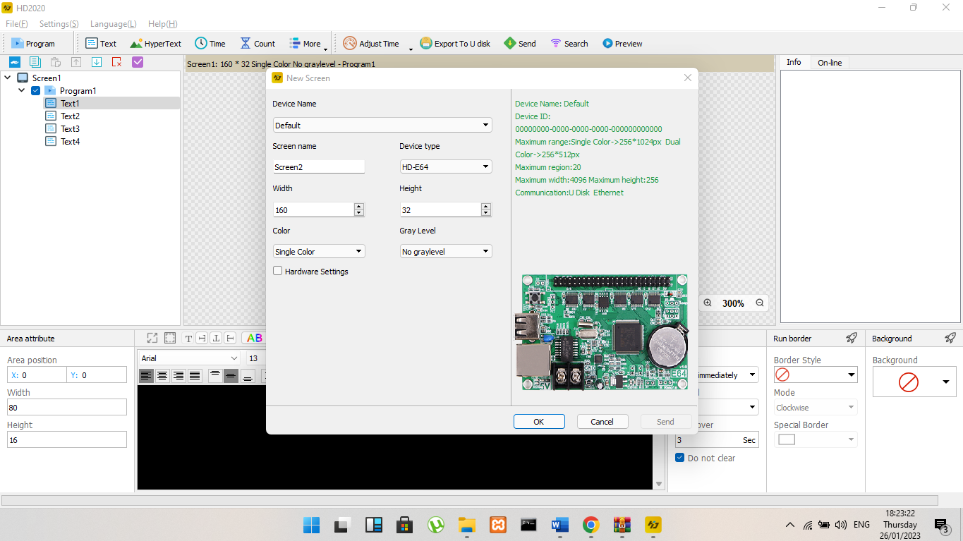
Method: Click File -> New Display, and the setting dialog box pops up.
Figure 16: Setting dialog box.
The control card already has the correct parameters (normal display text), create a new display screen, click OK, and complete the establishment of a display screen and a program. If the control card does not have the correct parameters (i.e., the text is not displayed normally), select the device, select the color, set the width, height, and gray level; then click to enter the hardware setting interface and set the display point method of the display, that is, commonly used smart settings such as: network cable, serial cable, or Wi-Fi for intelligent settings. Wi-Fi was used for Super Display.
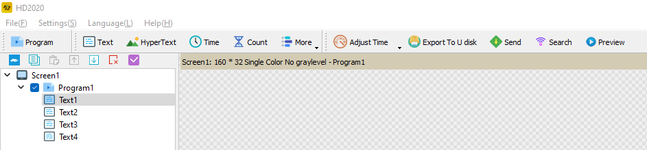
Create a new partition (second-level content, each program can be set up with 20 partitions)
Method: After selecting the program, click on the graphic, text, time, timing, counting, temperature and humidity, animated characters, Chinese calendar, etc. to create different types of partitions.
Figure 17: Different partitions as configured.
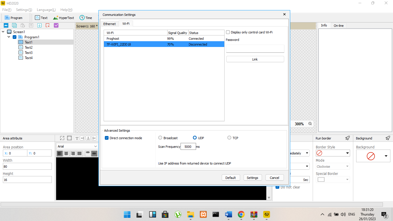
Communication settings (Wi-Fi card)
When the Wi-Fi card is connected, first connect the Wi-Fi signal sent by the control card (requires a computer with a wireless network card, if using a desktop computer, be sure to purchase a wireless network card; generally a laptop with a wireless network card is preferred).
When connecting to a Wi-Fi signal, the default password is “88888888”. If you connect with the HD 2020 software, you need to enter the password of “88888888”, Click Connect, and the default password can also be modified. Once Wi-Fi is connected, the device can be found in the software. The information window will appear on the online bar of the control card and other information.
Figure 18: Communication settings using the HD 2020 program.
Maintenance
Updating the scrolling text
The text can be updated via wifi (mobile or PC) or physical flash drive. The app required for the mobile control is called LedArt, this application has the ability to switch programs, change text, increase and decrease brightness of the super display wirelessly. The app required for PC control is the HD2020, the app gives the user the ability to fully control the display both wirelessly and through a flashdrive.
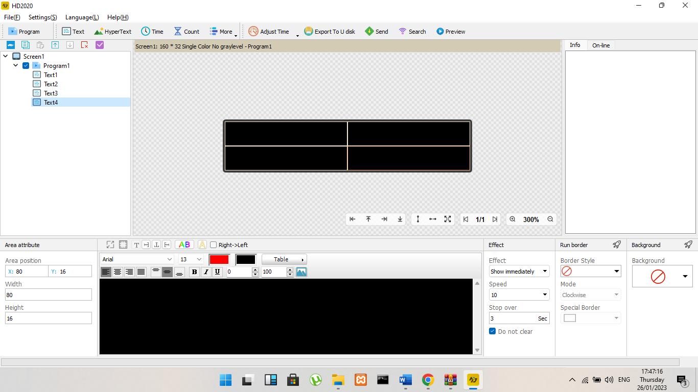
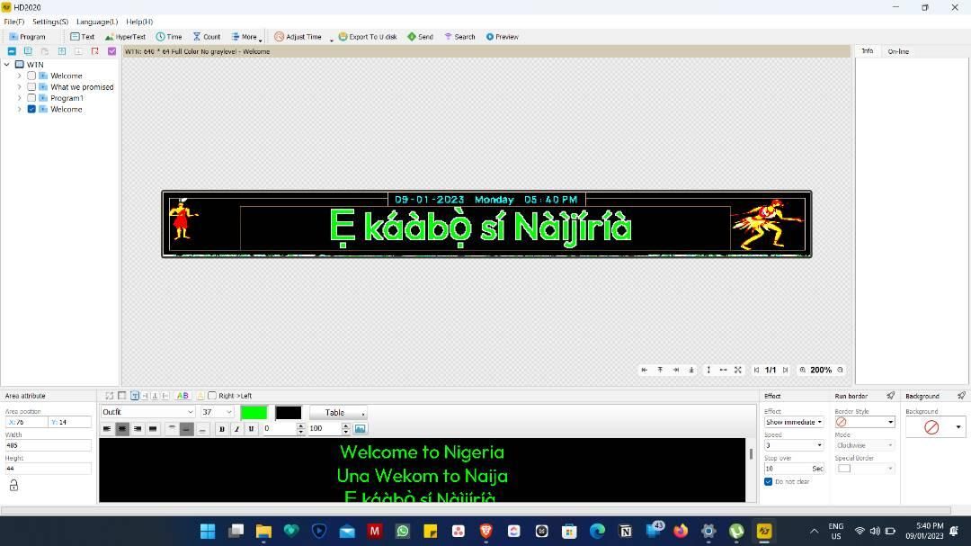
Figure 19: HD 2020 User Interface.
Changing the text and graphic display
For text-only content display, we use text areas to meet the requirements. The text supports left rotation, right rotation, and reverse. The table was customized, borders, and background were added.
The steps to change the text are:
Create a display screen.
Click the text, the text area appears (coordinates, width, and height can be set freely).
To change the language:
Click the text area.
Add language text.
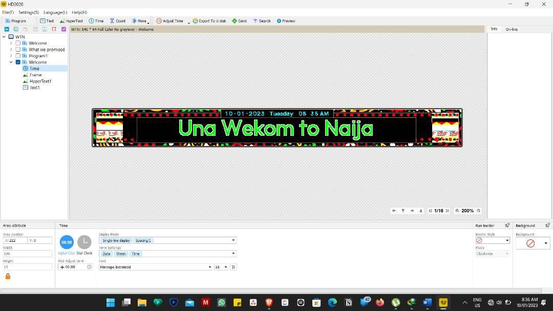
Figure 20: The text display of the HD 2020 software.
To change the graphics on the display the new design can be uploaded wirelessly or via usb through the PC application. There was an instance where we wanted to display pictures instead of text. We took the following steps:
Create a display screen.
Click the picture and text, the picture and text area (coordinates, width, and height can be set freely), add the picture to be displayed in the blue icon (see Figure 21).
Graphics were made by third party apps, like Corel Draw and Photoshop.
Figure 21: The graphic display of the HD 2020 software.
Battery check
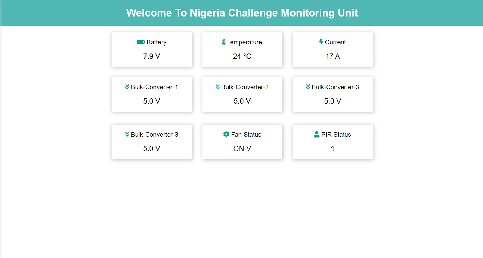
A custom PCB extension is available to wirelessly monitor the battery voltage and current consumption in real time. The board has 5 voltage sensors (voltage divider) that measures the voltage at each bulk converter and the battery and displayed on a localhost web server, the pcb is controlled by an ESP 32 microcontroller. To access the webserver connect the ESP 32 to your computer and open a serial port, copy the link and paste in your browser to view the life data.
Figure 22: The webserver for the Super Display unit.
Time and date
The LED controller used is the WF2LED controller which has the ability to display current time and date (CMOS) and this can be included in programs sent via the mobile or PC application. The time display on the display is similar to text and graphics. The steps are as follows:
Create a display screen.
Click the time, the time zone appears, the setting is relatively simple, and the location can be set, as shown in the Figure TK.
Extras
Time setting: Set the time on the control card, which can be the current time of the system, or it can be the elapsed or future time.
Brightness setting: divided into manual, automatic adjustment (requires additional sensor), three types of adjustment by time.
Timer power on / off: Set the startup time and shutdown time of the control card.
Startup screen: Enable the startup screen, click OK after loading the file, or export the file to a USB flash drive.
Firmware update: used to upgrade the control card.
Power-on prompt: Used to remove the power-on prompt of the control card, you can set not to display / show all / firmware version / control card & memory size.
Screen control: used to control the on / off / play / pause of the display.
Extensions
Electronics
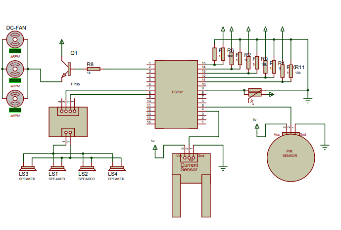
An extension for the super display includes 5 voltage sensors to measure the voltage at bulk converters, current sensor to measure the display’s total current consumption, a PIR sensor to measure human proximity, an mp3 module and a speaker to send a verbal message, a temperature sensor to measure the device temperature and a 4 DC fans for cooling. The entire board is powered by an esp32 microcontroller and all measured data is displayed on a localhost webpage.
Figure 23: Full schematic of the Super Display device.
Mechanical
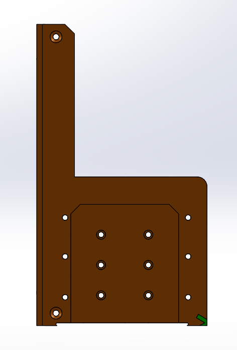
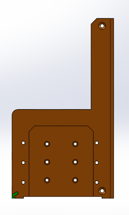
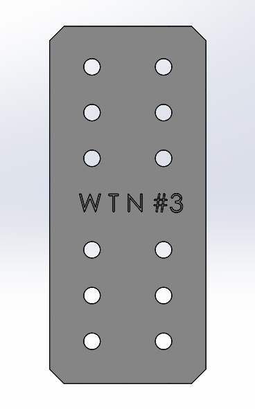
To use the electronic extension above, you’d need the elec. to disp. mount (see Mechanical Design files). Each mount requires three 3D printed parts.
Figure 24a (left): elec. to disp. top mount; Figure 24b (middle): elec. to disp. bottom mount; Figure 24c (middle): elec. to disp.LINK mount.
Figure 25: elec. to disp. mount assembly process (GIF).
 |||
|||